

Designing a Flying Fox System for a School Playground
Most people see a flying fox as simple playground equipment. Engineers see an alive, moving structural system that behaves more like a bridge under constantly changing forces.

DTCE recently completed the structural design for a double 22-metre-span flying fox system for a New Zealand school playground. While it appears simple from the outside, the project required careful consideration of dynamic loading, rider safety, terrain modelling, and foundation design. This is the story of what it actually involved and why projects like this are more interesting than they first appear.
Understanding How the Structure Actually Behaves
Unlike most playground equipment, a flying fox does not experience static loading. Once a rider starts moving across the span, the entire structure begins responding dynamically:
Cable tension changes
Support forces shift
Rider speed increases
Braking forces activate
Cable sag varies continuously
What appears to be a simple playground ride is actually a constantly changing interaction between the rider, the cable, the support structure, and the ground beneath it.
To better understand these interactions, DTCE developed a detailed SkyCiv cable model and analysed the flying fox using staged loading to simulate rider movement across the span. This allowed the team to assess cable sag, rider speed, and force transfer at different positions along the ride path, providing a more realistic representation of the structure's performance than a single simplified load case.
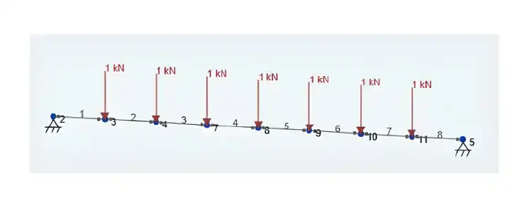
SkyCiv cable model with sequencing loads for 100kg
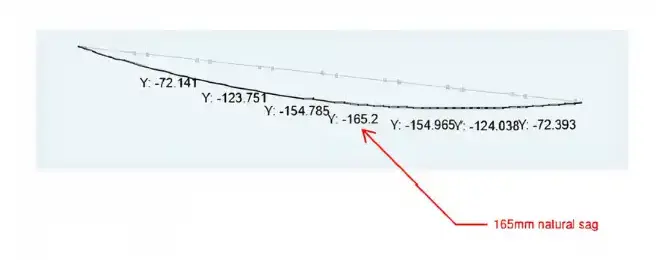
SkyCiv result of natural sag due to self-weight
The cables were modelled using their self-weight and unstretched length rather than an assumed tension force. This approach more closely reflects real-world installation conditions and provides a more accurate representation of cable behaviour.
Designing for the Full Range of Users
The flying fox was designed for a range of users, from 20 kg children through to 100 kg adults.
To verify performance under more demanding conditions, the system was also assessed against an ultimate load case using an equivalent 200 kg load with a 2.0 dynamic factor, representing the effects of rider movement and impact loading. Interestingly, the most critical design case was not simply the heaviest rider, but the changing forces created as the rider moved across the cable.

Modelling the Terrain Accurately
Before a single cable was tensioned or a pole was installed, we needed to understand the terrain. Flying foxes are deceptively sensitive to ground levels: even small changes in slope can affect how a cable behaves, how fast a rider travels, and how much clearance exists above the ground throughout the ride.
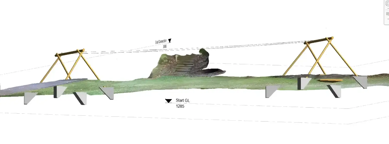
The flying fox spans 22 metres across sloping ground, with approximately 1.7 metres of natural fall along the ride path, which adds to the ride experience but also means the structural loads shift as a user moves along the span. Ground levels directly influence rider clearance, braking behaviour, and overall ride safety.
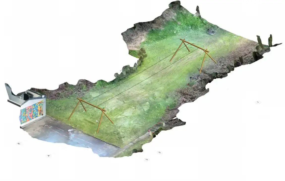
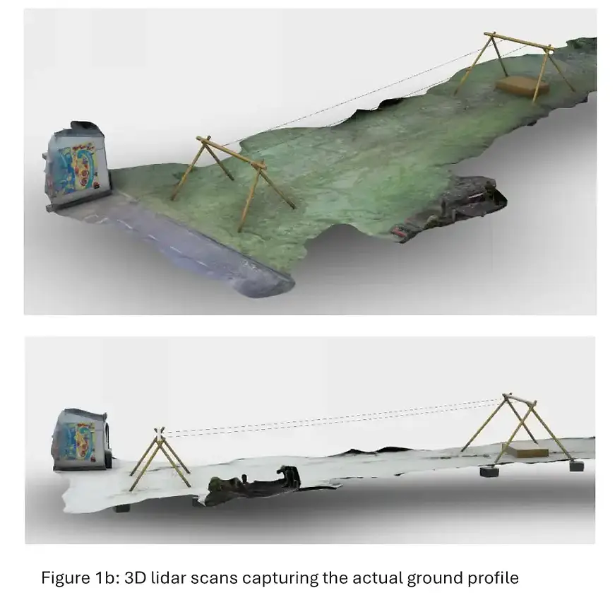
To capture the terrain accurately, DTCE completed a LiDAR scan of the site and developed a high-resolution 3D ground model. This provided a detailed understanding of the terrain and allowed the ride geometry, cable profile, and ground clearances to be assessed with confidence.
The model was then used to verify compliance with NZS 5828 requirements for seated cableway playground systems, helping ensure the flying fox would perform safely under a range of operating conditions.
Balancing Speed, Sag, and Rider Safety
One of the key parts of the design process was controlling how the cable behaves under load.
The twin wire ropes naturally deflect as riders move across the span. The challenge is finding the right balance between ride performance, user comfort, speed, and minimum ground clearance requirements.
Under heavier loading conditions, cable sag increases significantly, particularly near mid-span where forces become most critical. Even under the governing ultimate load case, the system maintained the minimum required seat-to-ground clearance specified by the standard.
Rider speed was also carefully assessed. The final system remains within the allowable speed limits for seated cableway playground systems while still providing a smooth and enjoyable ride experience.
The key outputs our structural model had to satisfy:
Minimum 400 mm seat-to-ground clearance at all points along the ride, as required by NZS 5828 for seated cableways.
Maximum travel speed of 6.0 m/s: our analysis showed the system peaks at approximately 5.4 m/s under the critical load case, comfortably within the limit.
Controlled braking at the termination end, with the spring-based stop designed to absorb energy over a minimum 2.4 m distance, providing smooth deceleration and avoiding abrupt stops.
Designing the Support Structure
Each end of the flying fox is supported by a timber A-frame system designed to transfer cable forces safely into the foundations.
While the structure itself appears relatively simple, the forces generated by cable tension can be substantial, particularly when both flying fox lines are loaded simultaneously.
The support system includes:
Horizontal timber poles acting as cable anchor points
Diagonal timber supports providing lateral stability
Reinforced concrete pad footings resisting uplift and overturning forces
Particular attention was given to uplift resistance, as cable tension can create significant upward forces within the support frame. The footing design uses embedded timber connections and soil mass to help stabilise the structure under operational loading.
Site Investigation and Ground Testing
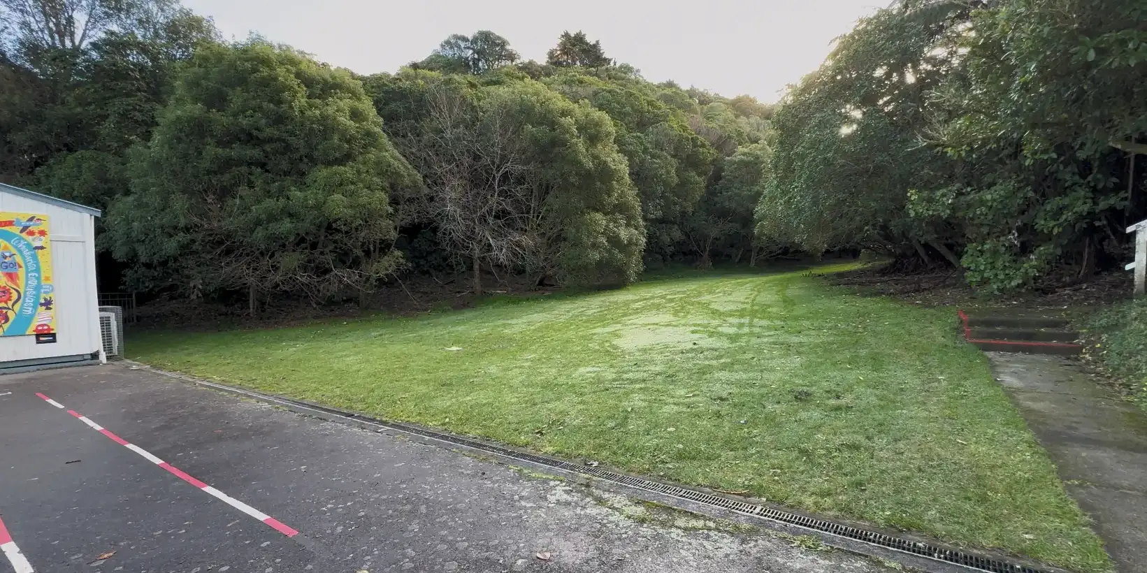
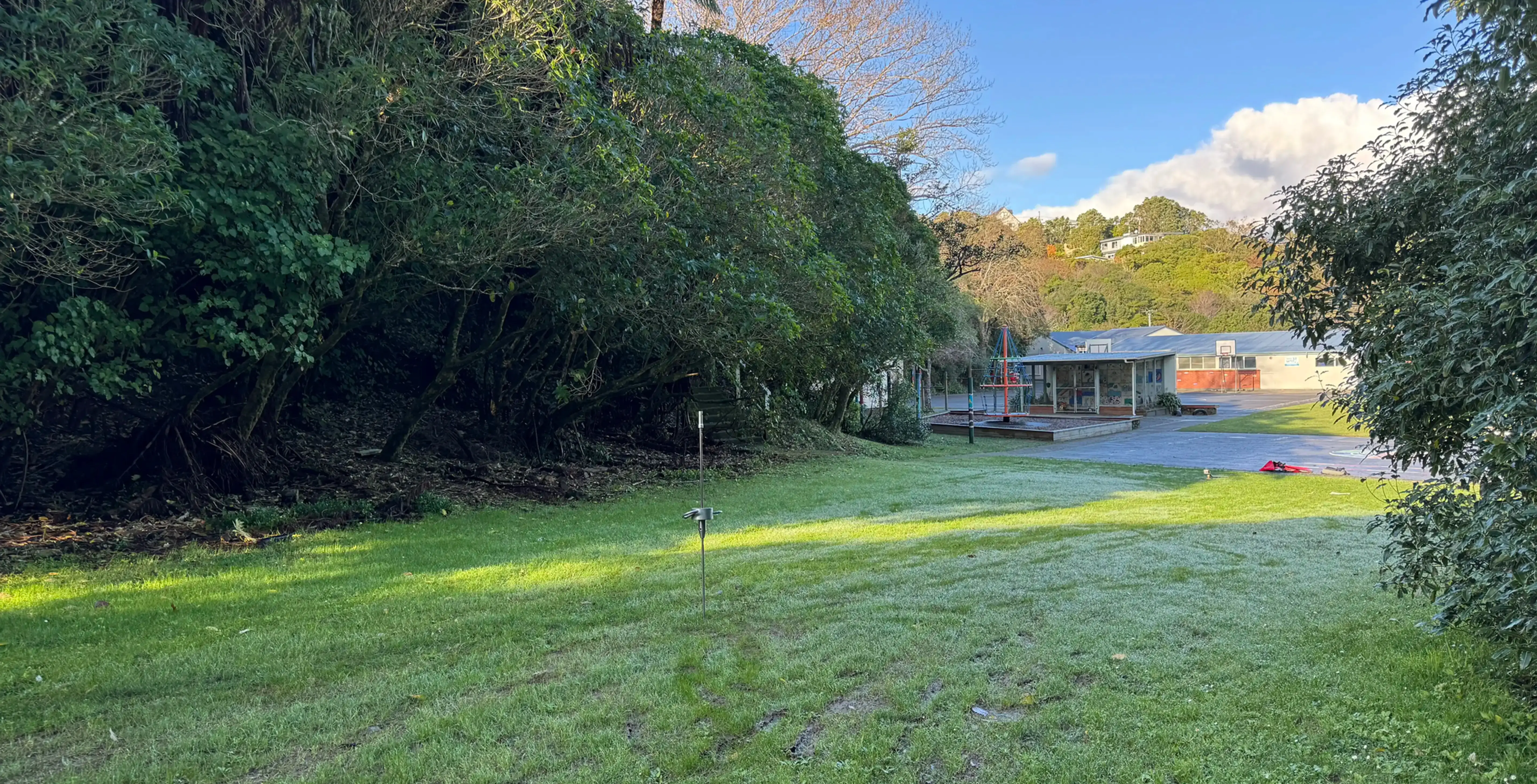
Before foundation design began, DTCE also carried out SSI Scala penetrometer testing on site to better understand the existing ground conditions.
The testing identified consistent firm ground conditions at relatively shallow depth across the site, which allowed the team to confidently determine the allowable bearing capacity for the pad footing design.
This information became particularly important because uplift forces, rather than gravity loads, governed the foundation design. As the flying fox cables are tensioned, significant uplift and overturning forces are generated within the support frames.

Using real site data allowed the footing design to be tailored specifically to the ground conditions on site, helping optimise the footing size while ensuring long-term structural stability. To resist uplift, the pad footings were embedded 0.4 metres below ground level, allowing the weight of the overlying soil to act as a stabilising mass.
This practical approach improved uplift resistance while keeping the footings compact and suitable for the site's spatial constraints.
Designing for Long-Term Public Use
Playground structures experience repeated daily loading, environmental exposure, and constant public use. Durability and maintainability therefore become just as important as the initial structural design.
The system also incorporates:
A spring-based braking system for controlled rider deceleration
Engineered woodchip surfacing beneath the ride path
Proprietary cable tensioning and trolley systems designed specifically for playground applications
Together, these elements help create a safer and more durable recreational structure for the school environment.
What Makes This Project Stand Out
Projects like this highlight how much engineering sits behind structures people often see as simple. Even relatively small recreational projects require careful consideration of dynamic loading, structural movement, safety compliance, site conditions, durability, and long-term performance. Flying fox projects sit at an unusual intersection of structural engineering, dynamic load analysis, geotechnical assessment, and safety standards compliance. On this project, we brought in LiDAR scanning where a standard survey wouldn't have been sufficient, built a staged load-sequencing model to track cable behaviour as a rider moves across the span, and grounded every design decision in site-specific soil data. |
For us, that is part of what makes these projects interesting. The engineering may sit quietly in the background, but it plays a critical role in creating safe, durable, and enjoyable spaces for the people who use them every day.

Interested in a playground, recreational, or community infrastructure project? Contact DTCE to discuss how we can help bring your project to life.


Comments